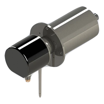
UEA’s Alpha Slip Rings, can be integrated either with cable storage reels or complex winch systems. When it comes to specifying cable reels and winch systems, here are five basic design considerations to keep in mind:

Drum & Flange size
Cables (or “tethers”) vary widely in their bend characteristics. The bend radius determines the diameter of the drum. Drum flanges must be sized to retain the cable when the full length is wound onto the drum. More winding layers increases the potential for winding difficulties, so it is best to keep the number of winding layers below 10 or 12 to minimize the risk of cable damage.
Slip Ring Mounting
Another consideration related to the size of the drum is where the slip ring can be mounted. Most commonly, the slip ring is mounted inside the drum. This type of mounting reduces the possibility of damage to the slip ring and helps reduce the overall envelope size of the system. In some cases, however, the center hole is too small, and it is necessary to mount the slip ring externally.
Motor horsepower and power supply
While cable reels may sometimes be driven manually, winch systems must be powered. When an electric motor is used, the following key questions should be considered:
- What type of power (AC/DC, voltage, # of phases) is available where the system will be located?
- How much weight will be pulled? (Don’t forget to include the weight of the cable itself along with any equipment.)
- What speed is required during reel in and out?
- Does the speed of the motor need to be controlled? A motor controller can be integrated to provide this capability.
Level Wind
For systems with cable lengths less than 1000 feet, a level wind system is generally not necessary, and the winding process can be controlled simply by increasing the flange height and keeping the flange-to-flange distance short. A guideline often used is that a level wind system is not required if the fleet angle is less than 1.5 degrees. The fleet angle is defined as the largest angle of the cable between the sheave and the drum flange relative to the center line of the drum.
If necessary, a level wind system can be provided, which can mechanically drive the sheave laterally in synchronous fashion with drum rotation to maintain perfect wind location.
Other Design Considerations
- Other options to consider for your application include braking needs, tension control, junction boxes for the rotating and stationary sides, and material requirements.
- For larger and heavier systems, the mounting style of the drum and frame (e.g., cage, A-frame) and lifting method for transport (e.g., 4-point eye bolts, forklift pockets) can be specified as well.
