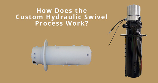
When a hydraulic swivel is needed, many applications require a custom hydraulic swivel be designed and built. We thought we would take some time to explain how the process of designing a custom hydraulic swivel works.
Designing a custom hydraulic swivel begins with communication between the client and the design engineer collecting information and asking questions. The client needs to provide general information such as number of ports, size of each port, the location and position of each port on the housing and spool, the operating pressure, and the function of each port.
Further discussion should be covered regarding the flow rate and the line velocity requirements of each port. Other points of concern are:
- How is the swivel to be assembled into the client’s equipment?
- Where is the torque arm located in respect to the mounting flange on the swivel?
- Can the mounting flange be welded to the housing or bolted?
- Is the swivel painted? If so, what’s the paint specification?
- If there is a slip ring included, what size of through hole is needed to pass through the wiring harness and connectors?
- Is the slip ring located above or below the swivel?
All of the collected information is then written up into a request for a quote.
The design engineer takes this information from the RFQ and begins the design layout process of the spool. The size of the through hole for the slip ring wiring harness and connectors needs to be determined and is located at the center of the swivel. The location of each port is laid out according to the client’s request. The size of each hydraulic circuit is designed to accept a certain flow rate using the recommended pressure line velocity of 25 ft/sec and the return line velocity of 10 ft/sec; unless otherwise specified by the client.
The flow rate, line velocity and hole size all have an effect on the port size for each circuit. The area of each flow groove around the spool is 1.5x that of the deep drill. Care must be taken to provide enough wall thickness between the bottom of the flow grooves and the edge of each deep drill to maintain a 4:1 safety factor. The wall thickness is determined by the operating pressure of each circuit.
The sum of all the circuit holes and flow grooves determines the bore size of a swivel. The bore size determines if the cap seals are located in the housing or in the spool. For swivels with smaller bores, the cap seals are located in the spool and the flow groove can be located in the housing or shared between the housing and spool. Swivels with larger bores the cap seals are located in the housing and the flow groove can be located in the spool or shared between the spool and housing. The preference is for the seals to be located in the housing.
It is preferred that the location of the low pressure circuits be at the ends of the swivel with the high pressure circuits positioned inboard. An energizer and cap seal are located between each circuit. If a high pressure circuit is located at the end of the swivel, a weep needs to be provided and connected to the return line back to the tank. The wear ring is the bearing element of the swivel and prevents contact between the housing and spool. The purpose of U-Cup seal is to contain and prevent hydraulic fluids from exiting the swivel. At each end, and internal to the swivel, are the excluder seals which keep particulate from entering the swivel. External to the swivel, and at each end, we have a thrust washer and o-ring. The o-ring prevents the larger contaminates from entering the swivel and the thrust washer prevents metal contact between the housing and spool.
The housing is usually rigidly mounted while the spool is allowed to float within the housing while its rotation is constrained. The torque arm controls the rotation of the spool. When the mounting flange is welded onto the housing, the material is steel tubing; and when the mounting flange is bolted to the housing we can use ductile iron trepanned tube.
If there is a slip ring, we prefer it be mounted above the swivel. If it’s located below, then a liquid tight connector needs to be added at the top of the swivel to prevent moisture from getting down into the slip ring.
This is how the flow of the custom hydraulic swivel process works.
